Symbols Library in TurboCAD Windows
 Symbols and parts, like Blocks and Groups, are a valuable part of any CAD application. While Blocks and Groups are internal to a drawing, library items are external files. Generally, symbols are stored in a file, and categories of symbols are stored in Windows directories that can be loaded as separate libraries. Any vector drawing that may be read by TurboCAD can be used as a symbol, not simply .TCW files. This means, for example, that a favorite collection of .SKP components may be used and loaded this way.
TurboCAD Pro Platinum comes complete with a number of sample .TCW symbols as well as a much larger collection of parametric parts. The parts are also kept in libraries and are accessed like symbols. The difference is that these parts are parametrically driven. Those parameters may also be revised after they have been inserted in the drawing. Parametric Parts may be created with the Parametric Parts Manager. Examples of these parts include desks whose length, or number of drawers, can be changed; bookshelves whose height, width, and number of shelves may be changed; and varieties of nuts, bolts, fittings, doors, and windows.
Special Symbols
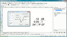
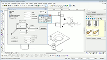
TurboCAD Pro Platinum also includes several special parametric symbols used in certain types of annotation that help in communicating with manufacturers. They include the Weld Symbol, Surface Roughness Symbol, Geometric Tolerance Symbol, and Adhesive Symbol. While these symbol are found in the Special Tools section, their output are actually parametric, editable symbols.The Adhesive Symbol is a parametric part (.PPM, see Parametric Parts Manager) and is therefore also an editable parametric 2D symbol. It may also adjusted through the Selection Info Palette. It includes dozens of parameters for the Surface Preparation, Application Method, Cure Method, Adhesive Physical Form, and Adhesive Technology Family. The Weld Symbol communicates finish, contour, depth of chamfer root penetration, groove angle and more. The Geometric Tolerance Symbol provides information about allowable deviations of form, profile, orientation, location, and run-out of a feature. The Surface Roughness symbol communicates the type of roughness, the minimum and maximum heights, waviness, and more.