TurboCAD Mac v14 Deluxe 2D3D Upgrade from Previous 2D/3D version
TurboCAD Mac v14 Deluxe 2D3D Upgrade from Previous 2D/3D version
(Support Upgrading from v7 - v12)
TurboCAD® Mac Deluxe2D/3D puts you in the driver’s seat of exceptional design. Whether you are a builder, manufacturer, maker, or student, you will be able to harness the power of 2D drafting and 3D modeling to design just about anything you can imagine.
Data Sheet
More Info
Overview
Shift into high gear with TurboCAD Mac Deluxe 2D/3D
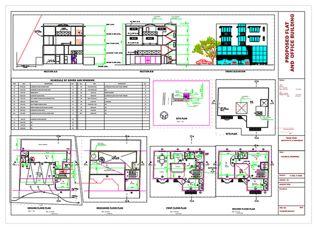
TurboCAD Mac Deluxe 2D/3D is a complete 2D/3D CAD solution that is extremely powerful, yet easy to use. Design with powerful 2D/3D drafting and ACIS® modeling tools. Quickly layout floor plans, diagrams, and illustrations. Our simple interface will speed up your workflow so that you can get more done in less time.
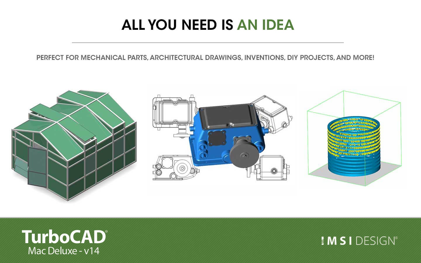
TurboCAD Mac Deluxe can help you design projects such as:• Architectural Drawings• Remodeling Plans • Prototyping with 3D Printers • Mechanical Drawings • Furniture design, woodworking, and cabinetry • 2D drafting, diagraming and schematic drawings • Custom manufacturing from CAD to CNC |  |
 |  |
Compatibility and file sharing
Whether you’re a team of one or many, you’ll have the interoperability needed to collaborate. We’ve ensured that TurboCAD is compatible with over a dozen popular CAD and Graphics formats. You will be able to deliver files that can be opened and edited by users of AutoCAD® andother popular design software. Your team will be running like a well-oiled machine.
| • TurboCAD Mac provides compatibility with AutoCAD®DWG and DXF files, from R12 to 2023 • STL Import/Export for 3D printing • SVG Import and Export • 3MF Import & Export • VMRL 2.0 Texture Support • OBJ Texture Support • Adobe Illustrator® Import • PDF Import • SketchUp 2023 Import/Export • Collada™ (DAE) Import/Export • Complete support for Metric and Imperial units | 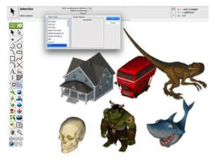 |
We will help you learn
While TurboCAD Mac is feature rich, we work hard at making it easy by including intuitive tools like our LogiCursor™ that makes CAD a snap by suggesting your next move as you draw.
Your purchase also includes access to our training tutorials, so you will not have to learn through trial and error. We are experts at creating CAD software and our tutorials will help you to become an expert user quickly.
Key Features
TurboCAD Mac Deluxe 2D/3D is loaded with 3D modeling and 2D drafting tools
TurboCAD Mac Deluxe 2D/3D provides solid modeling technology found in many higher-end products. You will have over 275 tools for 2D drafting and a complete set of 3D design tools at your command. Yet thanks to our user-friendly interface, you’ll be able to go from start to finish in no-time-flat.
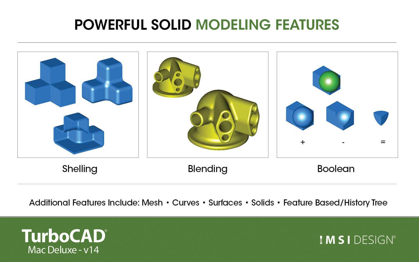
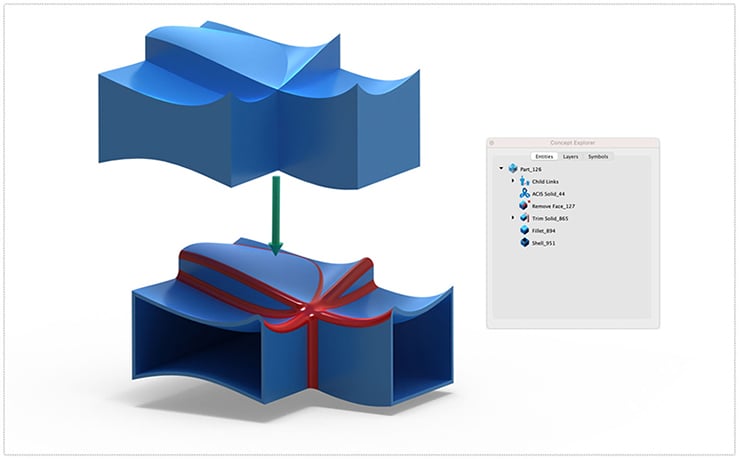
• Powerful 3D design tools including mesh, surface, and solid modeling
• 3D editing tools such as blending, chamfering, and shelling
• Complete design tool with extrusions, Booleans, and surface modeling.
• Precise geometry suitable for ‘concept to manufacturing’
• Automatically generate 2D drawings from 3D models
• Tools to create 3D from 2D shapes
• Over 275 tools for 2D drafting (text, dimensions, points, lines, arcs, etc.)
• 2D/3D Part Library of over 38,000 items
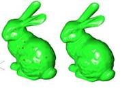
• 3D printing verification tools
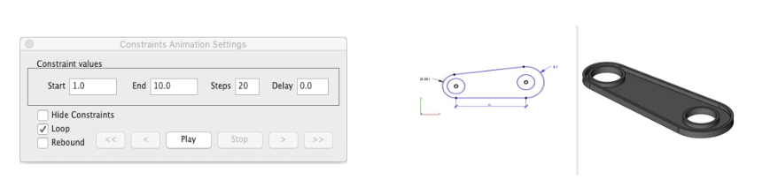
• 2D Geometric and Dimensional Constraints to manage geometrical relationships between 2D shapes!
 |
Intuitive Design and Editing Utilities
Drawing precisely is easy with TurboCAD Mac! We have designed it to be user friendly and intuitive to work with.
The LogiCursor™ anticipates your next action and guides your cursor to potential point selections in the drawing.
The Gripper adds drag and drop capabilities to make editing designs easy breezy.
Customizable Grids add another level of ease by providing precision drag and drop in rectangular, polar (circular), and isometric layouts.
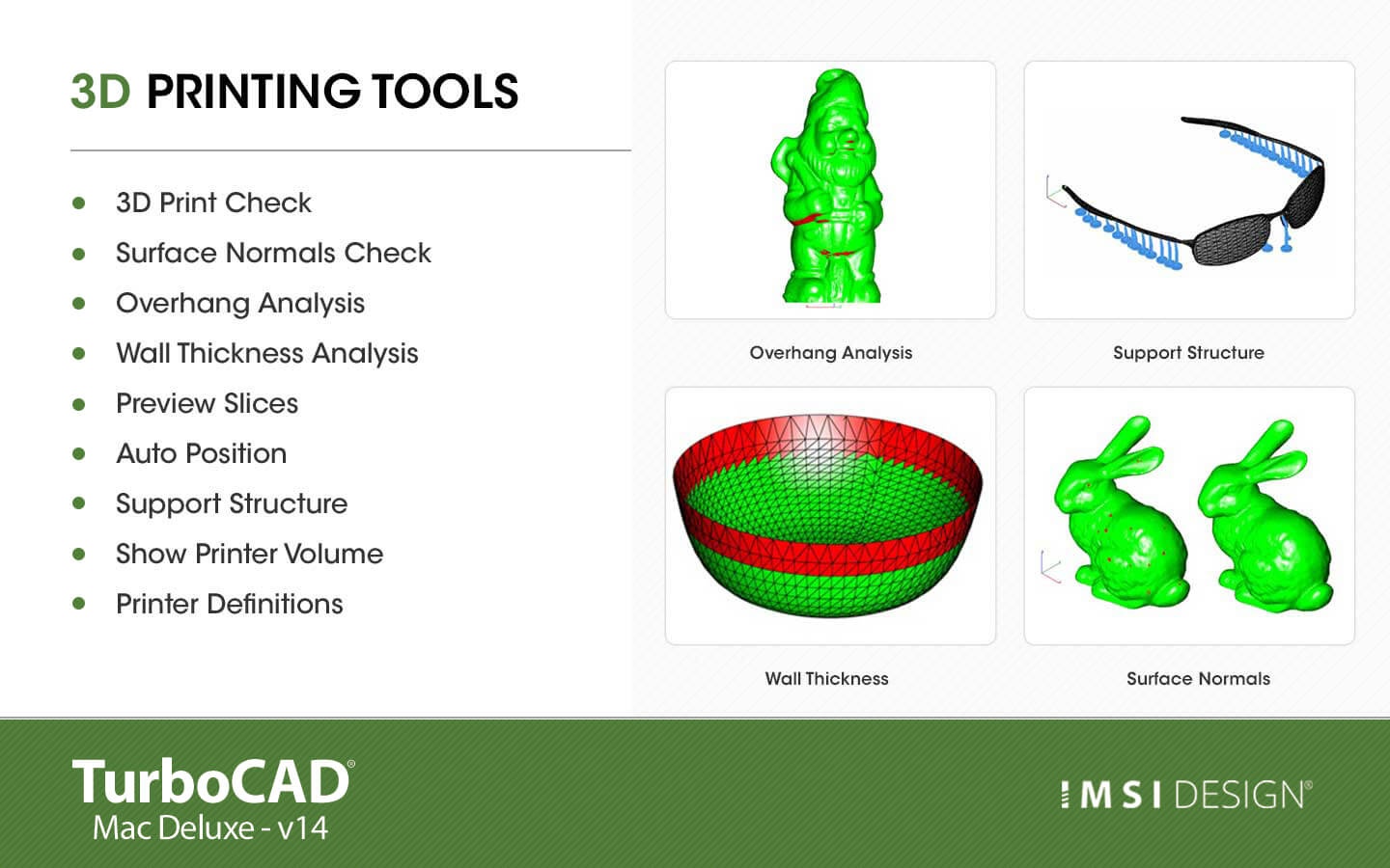
3D Printing Tools
TurboCAD Mac Deluxe 2D/3D includes 3D printing tools to prepare and validate your designs to make them 3D printer ready.
 |
3D Print Check
Checks for print viability, displaying warnings or errors to the user.
Surface Normals Check
Facet normals define the inside and outside areas of a part. If facet normals are pointing the wrong way, the 3D printer may have problems creating the part. This will check for problems and we have several commands that can help you fix it.
Overhang Analysis
This will help you visually inspect modeling areas that may require structural support for 3D printing. Meshes, surfaces, and solids facets normals are compared to the work plane direction. Angles that are less or equal to 45 degrees are highlighted as red.
Wall Thickness Analysis
This tool provides a means to visually inspect modeling areas that may be too thin for 3D printing. Meshes, surfaces, and solids facets are examined using ray intersections.
Preview Slices
This interface will help you to slice models given a direction and thickness. The dialog box allows for animation through the slices and single-stepping. Use to verify that a part has closed, non-overlapping sections, a requirement for 3D printing.
Auto Position
The Auto Position tool translates the model to the positive x, y coordinate system at z=0.
Support Structure
Manually adds geometry to support material as it is created by the 3D printer. Support structures controls, include Attach Radius, Midpoint Radius, Base Radius, Base Thickness, and Drag base and midpoints to modify structure location.
Show Printer Volume
Toggles the boundary of the default 3D Printer. The volume is defined within the Printer Definitions dialog box.
Printer Definitions
Sets key parameters of the 3D printer, including length, width, and height of the volume accessible by the printer. The parameters in the Printer Definitions dialog box are used for commands such as 3D Print Check and Auto Position.
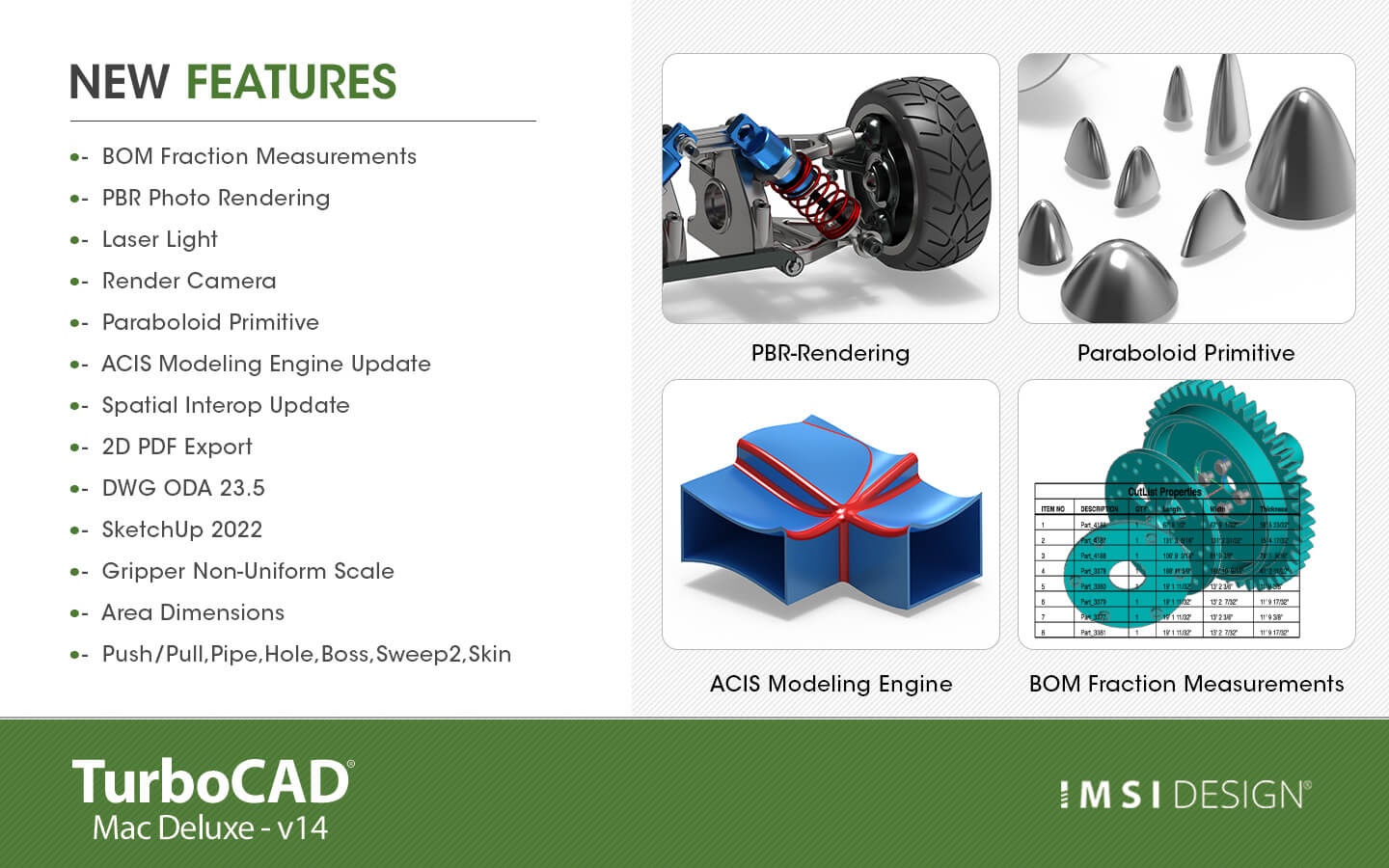
New Features
BOM Fraction Measurements
The Bill of Material Create BOM feature has a new option to support fraction measurements. To use this feature, select the Attributes and BOM dialog box from the Tools menu. Select your objects and associated a data set such as CutList properties. Apply to selected. Now select the Create BOM option to create a table. In the BOM Settings dialog box, select the Decimals pull down option. And then Select Fractions to display measurements as factions of feet and inches.
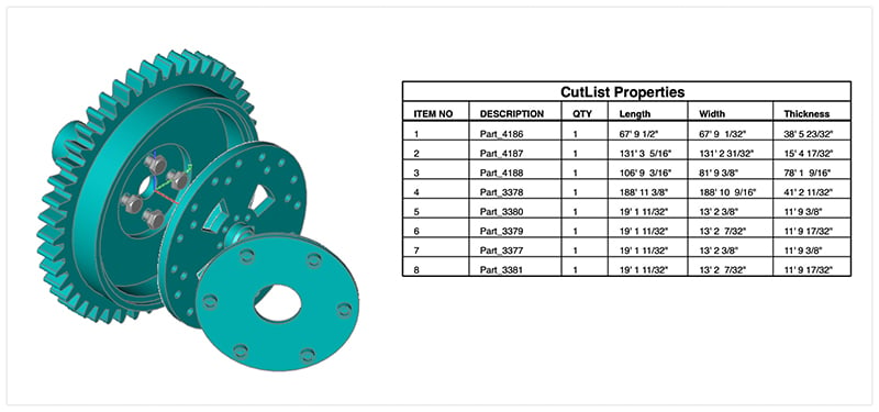
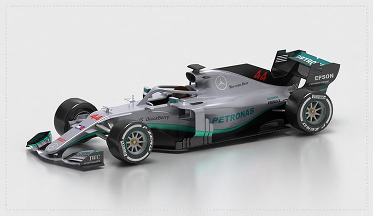
Photo Render Tool Palette
The Photo Render tool palette provides access to many of the tools used to create photo rendered images. The tool palette is access from the Tools menu bar “Photo Render” option.
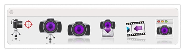
| • Create Camera | Creates a camera from eye point, reference point, and field of view. Cameras are saved with file and used with the Render Camera tool. |
| • Render Camera | Renders a selected camera to the window. |
| • Render Window | Renders the current window and view orientation. |
| • Render To File | Renders current view orientation to a file with new width/height. |
| • Display Last Render | Displays the last rendered window to drawing window. |
| • Render Settings | Dialog box with settings for HDRI, background, materials, and other settings. |
Create Camera
The Create Camera tool creates a camera object from eye point, reference point, and field of view. Cameras are useful for saving view orientations that can be recalled or used with the Render Camera tool. To create a camera:
1.Select the Create Camera tool from the photo render tool palette
2.Specify the eye point, defined as the camera location
3.Specify the reference point, which specifies where the camera is looking
4.The camera is created
Camera objects have two parameters that can be modified from the data entry window.
1. Field of View (size of viewing area)
2.Focal length (length of camera and controls perspective distance)
Render Camera
The Render Camera tool creates a photo rendered image from a selected camera.
Camera properties supported when using this command include:
Start Point representing the camera eye point
End point representing the camera reference point
Field of View defines the scope of the view
Cameras are always rendered with perspective enabled. The rendered image is drawn into the drawing window.
Render Window
The Render Window tool renders using the current view orientation. The results are displayed into the drawing window.
Render To File
The Render Window tool renders using the current view orientation. The results are displayed into the drawing window.
Display Last Image
The Display Last Image redraws to the window the last photo rendered image.
Photo Realistic Render Settings
The Render Settings dialog provides access to the following photo render settings and parameters.
• General Settings
• HDRI
• Backgrounds
• Sun & Sky
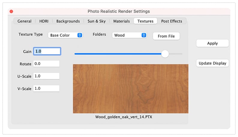
• Textures
• Post Effects
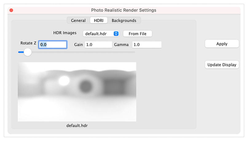
HDRI
The High-Definition Range Image (HDRI) tab provides access to the following settings and parameters:
| HDR Images | Drop drown containing example HDRI images |
| From File | Select a HDRI from file system |
| Rotate Z | Rotate the HDR from 0 to 360 |
| Gain | Increase or decrease the light intensity |
| Gamma | Increase or decrease the contrast of the HDR image |
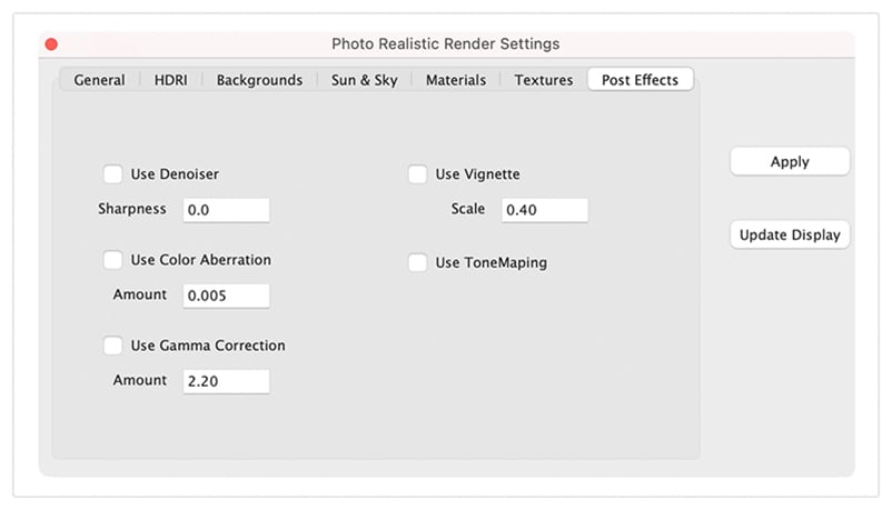
Post Effects
A post processor is a tool that allows you to apply various image-based effects to a rendered image after it has been completed. These effects can include things like tone mapping, denoising, color aberration, vignette, and gamma correction. Post processors can be very useful for improving the final appearance of a rendered image and can help to add a more polished and professional look to your work.
Post processors are accessed under the Post Effects tab in the render settings dialog box. The Post Effects tab is only available in SharkCAD, SharkCAD Pro, ViaCAD Pro, and TurboCAD Mac Pro.
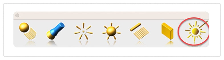
Laser Light
The laser light adds a direct light source that emits a focused beam of light. Laser Lights are defined by a start point, end point, radius, and gain. The start point defined the laser start while the end point defines the direction of the light. The radius value defines the cylinder region of light. The gain defines the strength of the light.
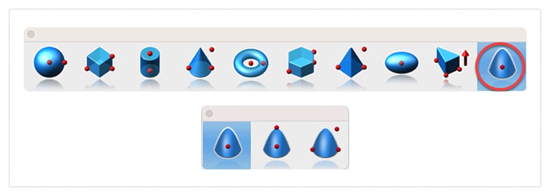
Paraboloid Primitive
The paraboloid primitive provides a means to create a quadric surface from one-, two-, or three-point definitions. Use a paraboloid to create a reflectors/radars, automobile headlights, solar furnaces, antennas, and aerodynamic tips. The Paraboloid primitive is located in the solid primitives tool palette, last tool item. The one-point paraboloid has a base center, and three radius values. The two-point paraboloid has a base center, end. The three point has two points defining the base diagonal, and one point defining the height. Each method provides a data entry window interface to change the associated radius values.
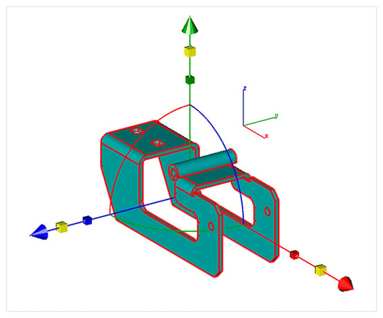
Gripper Non-Uniform Scaling
The Gripper has a new graphic widget to perform non uniform scaling via a handle. To use this feature, display the inspector and select the gripper properties tab. Then select “Enable Gripper”. The non-uniform scale graphic is the red, blue, or green box display along the associated axis. Select, hold and drag over the box to scale along that particular axis.
Red scales along x
Blue along y
And Green scales along z
You can scale curves, surfaces, or solids. Use the data entry window to scale a precise amount.
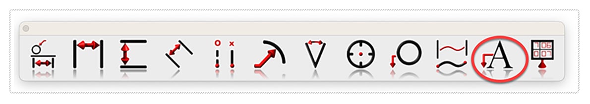
Area Dimension
A new dimension tool was introduced to support area-based measurements. To access the Area Dimension tool tear out the dimension tool palette and select the area dimension tool icon. The area dimension works with collections of closed curves or polygons. There are two options accessed through the data entry window.
1. Leader Line Dimension
2. Text at Centroid
Select Pick Leader Line Dimension. And now select the collection of curves or polygon. Then select the arrow location and text location. Now change the area method to text at centroid. And select the polygon. The area dimension is associative to the curves originally selected. Modifying a curve will update the area dimension. The Area dimension also work with a collection of curves used in a constrained system. In this case, updating any dimension value, will update the area dimension.
Spatial 2022 Update
Core technology components for the modeling and interoperability tools are provided by Dassault Systems Spatial Technology. V14 includes a major integration update for all products.
ACIS Modeling Kernel Update
The core modeling kernel was updated to support a newer version from Spatial. The new update provides greater increases in quality and robustness and improvements in modeling tasks such as booleans, blending, chamfering, sweeps, skinning, healing, and faceting functionality.
Interop Update
SAT & SAB UpdatesThe SAT and SAB data translators provide a neutral file format for precisely sharing curve, surface, and solid modeling data. Third party app supporting SAT/SAB file formats include AutoCAD, Inventor, Fusion 360, SolidWorks, and SolidEdge.
STEP & IGES UpdatesThe STEP and IGES translators for importing and exporting of precision curves, surfaces, and solids was updated via the Spatial Interop. STEP and IGES support sharing of precise NURB and analytic surfaces between applications.
SolidWorks, CATIA, PROE, NXNative format translators were updated to support newer versions from SolidWorks, SolidEdge, PRO E, CATIA, and NX.
The 2D PDF export is a new method of sharing vector and font-based data with other applications. Vector data such as Lines, arc, circles, and splines are supported. Additionally, text and dimensions annotations are supported. Line styles and pen weights are also supported. Surfaces and Solids are exported as wireframes.
The DWG, DXF, PDF, and DAE translators provided through the Open Design Alliance (ODA) were updated to support the latest enhancements and performance boasts. Additionally, minor enhancements were made supporting sharing of text and dimension data.
The SketchUp import/export technology was updated to support the lasted SDK. This includes support for newer versions as well as maintenance updates for sharing data between the applications.
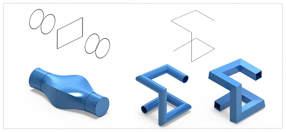
Ten new solid modeling tools were added into ViaCAD 2D3D and TurboCAD Mac Deluxe. These tools extend the already powerful solid modeling capability with the following tools:
- Two rail sweep
- Cutout Solid
- Protruded Solid
- Skin Solid
- Pipe
- Hole
- Boss
- Trim
- Push/Pull
System Requirements
TurboCAD Mac System Requirements:
Macintosh® OS 10.11 through 13.0 or higher¹, x64 Intel® Mac®, 3 GB of hard disk space, 8 GB RAM or greater, Mouse Pointing Device (wheel button recommended), OpenGL Compliant video card with 256 MB VRAM, ¹ Program compatibility is not guaranteed for earlier operating systems, require a machine with an operating system using x64 (64-Bit) architecture.